Introduction:
In the past decade usage of miniscrew implants has evolved as a mainstream orthodontic technique. [1],[2],[3],[4],[5] Miniscrew implants (MSIs) are a useful tool when absolute orthodontic anchorage is required. Miniscrew implants offer many advantages like , MSIs are of small sizes so they have good access to various placement sites(alveolar process, palate, retromolar and infranasal area, symphysis, or infrazygomatic crest ),can be loaded immediately, are easily adapted to routine Orthodontic mechanics, are low-cost devices , ease of insertion , ease of removal of the screws, no residual surgical defects. Also, they reduce treatment time when compared with conventional implants by the virtue of early loading. These benefits have led to a rapid rise in the popularity of miniscrew implants. While being helpful in many regards, miniscrew implants are not completely free from drawbacks and limitations. [6],[7],[8],[9],[10],[11],[12]
These complications include root injury, nasal and maxillary sinus perforation, nerve injury (inferior alveolar nerve, lingual nerve ) depending on the insertion site , MSI slippage or breakage, subcutaneous air emphysema resulting from the use of dental drills, MSI coverage by soft tissue, soft tissue irritation or hypertrophy, as well as inflammation causing the loosening of MSIs. Among these complications, root injury during MSI insertion is most commonly reported in the literature [6], [7], [8] The limiting factor here is the limited bone available between root surfaces, both with regard to the safety of root surfaces and stability of miniscrewimplants. To ensure optimal periodontal health and implant Stability, it is recommended that a minimum of 1 mm Clearance is necessary around the MSI. Miniscrew implants with diameter greater than 1.2- 1.3 mm are known to have better stability. [8] So, to provide adequate clearance, interradicular spaces greater than 3.1 mm has been suggested as “safe zones” for miniscrew implants of 1.2 mm- 1.3 mm diameter.[10] Even minor deviations of as little as 150 from the ideal path can damage the roots when inserting longer implants, leading to cemental tear and pain to the patient.[11]
Precise placement of the miniscrew implant would need some means of locating the desirable location of the interradicular bone between the adjacent roots. Clinically, it is almost impossible to place a miniscrew implant exactly between the roots without using some type of guidance device.[13] Numerous designs for placement of miniscrew implant are described in the literature like custom made soldered wire guides[14],[15], wire eyelets[16],[17] , X-ray pin[18] and surgical stents [19],[20],[21] placed over the interradicular area. This article presents a simple and economical method to make a mesh grid for precise implant placement. Mesh grid aids in locating the exact site over the IOPA/RVG radiographic image for insertion of miniscrew implant. Also, it helps in the accurate placement the miniscrew implant.
Fabrication Of Grid For Miniscrew Implant Placement
Many methods have been adopted in the past to fabricate the grid.[14], [15] Most common methods have been, spot welding multiple numbers of rectangular stainless steel wires[15] or multistranded ligature wire[14] to form the grid design. By obtaining the mesh from stainless steel tea strainer or flour sieve, we have reduced the effort, skill and time needed to make the mesh grid. Also, the sizes of the hole are smaller and uniform in size, which increases the accuracy of the guidance device. Advantage of mesh design is that it offers reference point in vertical as well as horizontal direction. [13]
1) Grid Design And Fabrication
1. Procure stainless steel mesh from commonly available stainless steel tea strainers or flour sieve (Fig.1). The mesh obtained from these sieves generally has square shaped holes (unit cells) of uniform size.
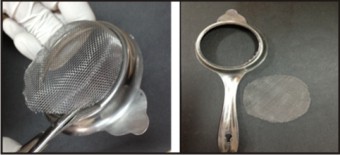 | Figure 1 : Mesh Being Cut Off From Commonly Available Stainless Steel Tea Strainer
 |
2. Count 10 cells on this mesh horizontally accounting for 10 column and 8, 10, or 12 cells vertically, accounting for that many rows in the grid. Cut out this much portion of mesh (Fig.2). Bend 0.016”x0.022’’ stainless steel wire to fit over the mesh as shown in the figure to form the grid framework (Fig 3).
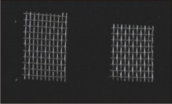 | Figure 2 : Mesh Piece Cut After Counting The Desired Number Of Unit Cells Horizontally And Vertically
|
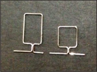 | Figure 3 : Grid Framework Made By Bending Rectangular Stainless Steel Wire..
|
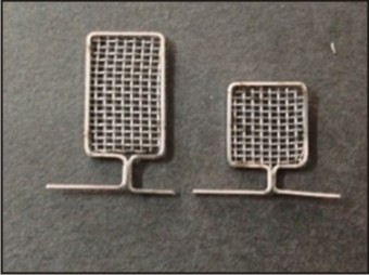
3. Dimension of the square hole (unit cell) is about 1x1 mm2 dimension. Width of the grid would be about 5mm on either side, so the total width of the grid is 10 mm. The height of the grid can vary depending on the location of teeth i.e. depending on the depth of the vestibule.
4. Spot weld the mesh carefully to the grid framework; so as to keep the square shaped holes of the mesh parallel to the grid framework (Fig.4). Mesh grid is ready to be used. Grid of different widths and heights can be made and stocked for use.
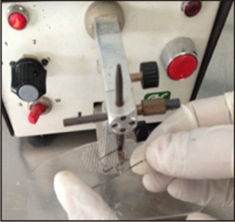 | Figure 4 : Spot Weld The Stainless Steel Mesh To The Grid Framework
|
2) Method To Use The Grid
1. Insert the wire ends of the grid framework to molar tube and premolar bracket or the brackets of the adjacent teeth in the desired location and ligate with the elastomeric modules (Fig 5). Choose the row approximating the junction of movable and attached gingival, fog e.g. in our patient the third row from upper border of grid frame (Fig. 6).
 | Figure 5 : Final Grid For Precise Placement Of Miniscrew Implants.
|
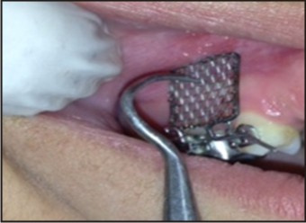 | Figure 6 : Wire End Of The Grid Inserted In Molar Tube And Ligated To Premolar Bracket. Choose The Desired Level (Row) Clinically
|
2. Make an IOPA/RVG radiographic image of the inserted grid with paralleling technique. Over the IOPA/digital image, locate the square that falls in the safe zone of the interradicular bone in the third row of the grid i.e. the sixth square hole in this patient (Fig.7).
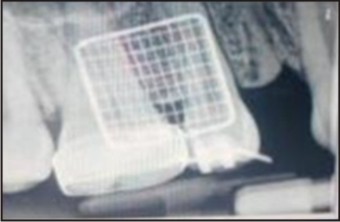 | Figure 7 : IOPA / RVG Radiograph Made By Paralleling Technique. Choose The Column In The Safe Zone Between The Adjacent Roots (I.E Sixth Column From Front Border Of The Grid)
|
3. Locate the same square hole of the mesh in the patient mouth. Using a probe tip through this hole make a bleeding point over the anaesthetized gingiva (Fig 8). This would be the ideal entry point (planned insertion point i.e. PIP) to put the miniscrew implant tip. Place the microscrew implant tip carefully at the desired position with the manual screw driver (Fig. 9). Insert the miniscrew implant firm controlled pressure, perpendicular to the bone surface. Confirm the correctness of the implant placement with a radiograph (Fig. 10).
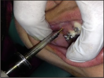 | Figure 8 : Miniscrew Implant Being Placed
|
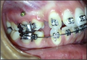 | Figure 9 : Miniscrew Implant In Place
|
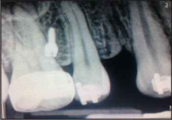 | Figure 10 : IOPA / RVG Radiograph To Confirm The Position Of The Miniscrew Implant
|
Discussion:
The use of a guidance device can facilitate accurate mini screw implant placement.[13] The careful localisation of ideal clinical and radiographic implant site before miniscrew implant placement helps to locate the safe zone in the interradicular area. This reduces the chances of impinging important anatomic landmarks (roots /nerves and blood vessels) and increases the stability of the miniscrew implants.[9], [10]
A variety of techniques [14], [15], [16], [17], [18], [19], [20], [21] involving wire guides, mesh grids, x ray pin, surgical stents have been reportedly used to facilitate safe placement of miniscrew implants in the interradicular area. Surgical stents/guides[19], [20], [21] give better three dimensional controls for miniscrew implant placement but fabrication of these guides is complicated, expensive, time consuming and requiring laboratory equipments.
The recommended method to obtain the radiographic image of any guidance device placed over the interradicular area is the paralleling technique using orientation rims. Radiographic standardization is of utmost importance while planning implant insertion site.[13], [18], [22] Any error in the x-ray source orientation to the positioning guide and the film/sensor can lead to misjudgement and wrong choice of implant insertion site. 0.016”x0.022’’ size has been chosen so that there is enough play between the wire ends of grid and bracket slot, this allows the grid to move freely towards the soft tissue surface (gingiva). Close approximation between grid and gingiva allows accurate radiographic imaging, which is mandatory to find the planned insertion point (PIP). Interpretations of radiographic distortions or inaccuracies in paralleling technique may result in false-negative or false-positive results.[22]
A comparative study by Thakur A et al[13] has reported that grid guides are more consistent than X-ray pin and wire eye guides. The small size of the mesh cells increases the accuracy of locating the geometric centre between adjacent root surfaces. Also the number of radiographs required in grid guides is lesser as compared to other methods. Grid guides provide reference point in both horizontal and vertical directions.
Conclusion:
The presented method has provided a simple, easy and economical method to obtain small sized unit cells for the mesh grid. Procuring the stainless steel mesh from tea strainer or flour sieve can reduce the effort, skill and time needed to prepare the mesh. Also, multiple numbers of grids can be made with the entire length of mesh cut off from the tea strainer/ flour sieves. In previous studies multiple numbers of stainless steel wire pieces were spot welded together in very precise manner to get the grid design. Those methods are very sensitive and need skill to get small sized mesh unit cells. By using commonly available materials, a very simple, easy, precise and economical method to fabricate the mesh grids in the clinic for miniscrew implant placement has been presented. Also, the grid has been used to successfully locate the ideal insertion site for miniscrew implant placement reducing the chances of root injury.
Refrences:
1. Kanomi, R.: Mini-implant for orthodontic anchorage, J. Clin. Orthod. 31:763-767, 1997.
2. Park, H.S.; Bae, S.M.; Kyung, H.M.; and Sung, J.H.: Micro- Implant Anchorage for treatment of skeletal Class I bialveolar protrusion, J. Clin. Orthod. 35:417-422, 2001.
3. Kyung, H.M.; Park, H.S.; Bae, S.M.; Sung, J.H.; and Kim, I.B.: Development of orthodontic micro-implants for intraoral anchorage, J. Clin. Orthod. 37:321-328, 2003.
4. Park, H.S.; Kwon, O.W.; and Sung, J.H.: Microscrew implants anchorage sliding mechanics, World J. Orthod. 6:265-274, 2005.
5. Carano, A.; Velo, S.; Leone, P.; and Siciliani, G.: Clinical applications of the Miniscrew Anchorage System, J. Clin. Orthod.39:9-24, 2005.
6. Kuroda S, Yamada K, Deguchi T, Hashimoto T, Kyung HM, Yamamotod TT. Root proximity is a major factor for screw failure in orthodontic anchorage. Am J Orthod Dentofacial Orthop 2007; 131:00.
7. Kadioglu O, Büyükyilmaz T, Zachrisson BU, Mainod BG.Contact damage to root surfaces of premolars touching miniscrews during orthodontic treatment. Am J Orthod Dentofacial Orthop 2008; 134:353-60.
8. Liou EJW, Pai BCJ, Lin JCY. Do miniscrews remain stationary under orthodontic forces. AJODO 2004; 126 (1) 42-47
9. Chaimanee P, Suzuki B, Suzuki EY. ‘‘Safe Zones’’ for miniscrew implant placement in different dentoskeletal patterns. Angle Orthod. 2011; 81:397–403.
10. Poggio PM, Incorvati C, Velob S, Carano A. “Safe Zones: A guide for miniscrew positioning in the maxillary and mandibular arch. Angle Orthod 2006; 76:191–197.
11. Kido H, Schulz EE, Kumar A, Lozada J, Saha S. Implant diameter and bone density: effect on initial stability and pull-out resistance. J Oral Implantol. 1997; 23(4):163-169.
12. Miyawaki S, Koyama I, Inoue M, Mishima K, Sugahara T, and Takano-Yamamoto T. Factors associated with the stability of titanium screws placed in the posterior region for orthodontic anchorage. Am J Orthod Dentofacial Orthop 2003; 124: 373–78.
13. Thakur A, Toshniwal NG, Misal A, Mathur A .Comparison of accuracy of various positioning guides used for determination of implant placement site using RVG.J Ind Orthod Soc 2012;46 (2):70-76.
14. Rachala MR , Aileni KR, Bukhari SAA, Nagam SR.Tray –Grid Guide for accurate mini-implant insertion. J Ind Orthod Soc 2012; 4(2):109-112
15. Reddy KB, Kumar MP, Kumar MN.A grid for guiding miniscrew placement. JCO 2008; 9:531-32.
16. Alle RK, Suma T. A simple wire guide for positioning micro implants. J Ind Orthod Soc 2010: 60-61
17. Hyung Choi, Tae Kim, Hye Kim. A precise wire guide for positioning interradicular microscrew guide,J.Clin. Orthod. 12(5):258-61, 2007.
18. Ludwig B, Glasl B, Leitz T, Kopp S. Radiological location monitoring in skeletal anchorage: introduction of a positioning guide. J Orofac Orthop 2008; 69: 59-65.
19. Suzuki, E.Y. and Buranastidporn, B.: An adjustable surgical guide for miniscrew placement, J. Clin. Orthod 2005;39:588-590,
20. Cousley, R.R. and Parberry, D.J.: Surgical stents for accurate miniscrew insertion, J. Clin. Orthod. 40:412-417, 2006.
21. Morea, C.; Dominguez, G.C.; Wuo, A.V.; and Tortamano, A.: Surgical guide for optimal positioning of mini-implants, J.Clin. Orthod. 39:317-321, 2005
22. Bowman SJ. Thinking outside the box with miniscrews. In: McNamara JA Jr, ed. Microimplants as Temporary Orthodontic Anchorage. Ann Arbor: Craniofacial Growth Series; 2008:45:327-390
|